1. Outline
FRS-DEMO-B is designed for Walkie Talkie transceiver module SR-FRS-1W and SR_FRS_0W5 demonstration, it can be used for both UHF(400M-480M)and VHF (136M-174M);it also can be used for voice intercom and data transfer demonstration; it is easy to set all the module parameter via the USB interface; When select the channel, it would voice broadcast the current channel number; You may quickly evaluate our module performance by the demo board, Just make a little modify, it can be directly applied into your real production.
2. The Demo board performance:1- The power switch, volume adjust , Channel selection switch 3 in 1;16 channels can be selected by the encoder switch;
2- It is easy to switch the VOX(Sound control transmit) by a VOX switch, the VOX level can be set via the PC;
3- Voice broadcast for the channel number, Chinese/English could be selected.
4- Monitor function by press [MON]key;
5- Voice intercom demo;
6- Data transfer demo;
7- One group user interface: SQ, LINE_IN, LINE_OUT, PTT, GND
8- Could restore to the factory parameter setting
9- The demo board parameter can be set via the USB interface, for the setting instruction please contact us to get the 《SR_FRS_1W UART communication protocol》 and《SR_FRS_0W5 UART communication protocol》
- Tx frequency, Rx frequency can be set alone;
- Tx CTCSS, Rx CTCSS can be set alone;
- Rf output power can be set by software;
- Commanding setting;
- Transmit Busy lock setting;
- Squelch level setting
- GBW bandwidth setting
- MIC sensitivity setting
- Scramble setting
- Volume setting
- VOX level setting
- TOT setting(Timer of transmit)
- Auto power save setting
- Data transfer
- All setting can be kept when power off
3. The demo board function define picture
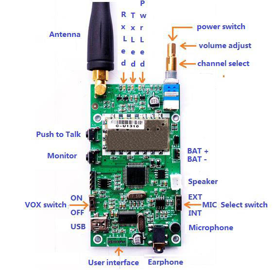
1) The demo board size: 45 mm X 90 mm;
2) DC power supply :3.3V-5V;
3) USB type: MICRO USB;
4) User interface:SQ, Line _in, Line_out, PTT, GND; When use Line_in,Should push the MIC selection to “EXT”position;
5)LED:
Red : DC power indication;
Yellow: Transmit status indication
Blue: Receive signal indication
4. The demo board operation 4.1 The voice intercom
1. Please mount the power, antenna, speaker; Push the MIC select switch to ‘INT’ position;
2. Power on the demo board , the power indication LED(red) turns on, Then rotate the volume adjust switch to a proper position; After about 1 seconds, the demo board would voice broadcast the current channel number;
3. Adjust the channel selection switch, ensure the transmitter and receiver are at the same channel;
4. Hold on the [PTT] key, the transmit indication LED(yellow) turns on, You may talk to the opposite side; After finished the talking, release the [PTT] key, the system automatically into the receive statues, When received the signal from the opposite side, The receive indication LED(blue)turns on;
5. At weak signal area, you may hold on the[MON] key, the system into monitor mode, release the [MON]key, the monitor mode is cancelled;
6. The frequency and the CTCSS for every channel can be set alone via the USB interface;
4.2 The sound control(VOX) 1. Push VOX switch to ON position, the VOX function is enabled, You may talk without [PTT]key, the system will automatically into transmit status.;
2. During the VOX valid status,The transmit indication LED(Yellow) turns on;When VOX enabled, the [PTT] key is still valid;
3. Push VOX switch to OFF position, the VOX function is disabled, you can only intercom by press the [PTT] key;
4. The VOX sensitivity can be set via the USB interface;
4.3 Earphone 1. The demo board can use the earphone, The speaker, microphone, and [PTT] key are integrated in the earphone, You may make the intercom just by operate the earphone;
2. Please be noted that the earphone socket may not be compatible with the 3’rd party earphone;3. If you need the earphone, please contact us;
4.4 User interface1. The demo board provide some useful interface for the user SQ: 0: with valid receive signal; 1: without receive signal; Line_in: May connect to an external Microphone, or an external audio source; MIC select switch” must at the “EXT” position;Line_out:The Frs module audio frequency directly output, Not via the audio amplify;PTT: 0: Transmit; 1:Receive;GND: GND;
4.5 Restore to the factory setting1. Power off;
2. Press the [PTT] and hold on, then Power on; When the transmit indicate LED fast blink, you may release[PTT] key;
3. When finished the system initialization,Transmit indication LED turns off,The system into the standby mode;
4.6 Data transfer/SMS transfer1. Connect the Demo board USB and the PC usb by MICRO USB cable;
2. Send command:AT+DMOMES=[Length]xxxxxxxxxxxFor the detail of the command ,please refer the UART communication protocol;For how to make the data transfer please refer “
4.7 USB interface for parameter settingUSB interface for parameter setting1. Firstly, you must install the USB driver,please download from the link:
http://www.prolific.com.tw/US/ShowProduct.aspx?p_id=225&pcid=41 NOTES: The USB 2 COM chip for this demo board is PL2303HX, it can only support the OS to WIN7, if you want support the OS to WIN8, please replace the PL2303HX with PL2303TA; 2. Power on the demo board, Connect the demo board and the PC with the Micro USB cable. 3. The COM port parameter setting
Baut rate: 9600 Data:
8parity bit: NoneStop:
1 4. Demo board parameter setting1) When you want set the frequency for some channel, You must rotate the channel selection switch to proper channel position firstly; Here is a example for GROUP COMMAND Setting:AT+DMOSETGROUP=0,450.0500,450.2500,1,2,2,0The parameter contents are as below in turn: 0:Narrow 450.0500:Transmit frequency (MHZ) 450.2500:Receive frequency (MHZ)
1:Receive CTCSS
2:Squelch level
3:Transmit CTCSS
0:Rf output power :1W, Companding:OFF, Busy lock:OFF

The other parameter setting is same as the Group setting, Please refer 《SR_FRS_1W UART communication protocol》 and 《SR_FRS_0W5 UART communication protocol》
5. The default parameter for demo board:
5.1 UHF(400M-480M) demo board
1. Band width:Narrow
2. Squelch level: 2
3. VOX sensitivity:64. MIC sensitivity:65. Volume:66. Scramble:OFF7. Tx output power:1W (valid only for SR_FRS_1W) ;8. Companding:OFF9. Busy lock:OFF10.TOT(Timer of Transmit):3minutes11.The default frequency and CTCSS
| Channel | Transmitfrequency(MHZ) | Receive frequency(MHZ) | TransmitCTCSS | ReceiveCTCSS |
| 1 | 450.0500 | 450.0500 | 0 | 0 |
| 2 | 450.0750 | 450.0750 | 0 | 0 |
| 3 | 450.1000 | 450.1000 | 0 | 0 |
| 4 | 450.1250 | 450.1250 | 0 | 0 |
| 5 | 450.1500 | 450.1500 | 0 | 0 |
| 6 | 450.1750 | 450.1750 | 0 | 0 |
| 7 | 450.2000 | 450.2000 | 0 | 0 |
| 8 | 450.2250 | 450.2250 | 0 | 0 |
| 9 | 450.2500 | 450.2500 | 0 | 0 |
| 10 | 450.2750 | 450.2750 | 0 | 0 |
| 11 | 450.3000 | 450.3000 | 0 | 0 |
| 12 | 450.3250 | 450.3250 | 0 | 0 |
| 13 | 450.3500 | 450.3500 | 0 | 0 |
| 14 | 450.3750 | 450.3750 | 0 | 0 |
| 15 | 450.4000 | 450.4000 | 0 | 0 |
| 16 | 450.4250 | 450.4250 | 0 | 0 |
5.2 VHF(136M-174M)demo board
1. Band width:Narrow;
2. Squelch level: 2;
3. VOX sensitivity:64. MIC sensitivity:65. Volume:66. Scramble:OFF7. Tx output power:1W (valid only for SR_FRS_1W) ;8. Companding:OFF9. Busy lock:OFF10.TOT(Timer of Transmit):3minutes11.The default frequency and CTCSS
| Channel | Transmitfrequency(MHZ) | Receive frequency(MHZ) | TransmitCTCSS | ReceiveCTCSS |
| 1 | 150.0500 | 150.0500 | 0 | 0 |
| 2 | 150.0750 | 150.0750 | 0 | 0 |
| 3 | 150.1000 | 150.1000 | 0 | 0 |
| 4 | 150.1250 | 150.1250 | 0 | 0 |
| 5 | 150.1500 | 150.1500 | 0 | 0 |
| 6 | 150.1750 | 150.1750 | 0 | 0 |
| 7 | 150.2000 | 150.2000 | 0 | 0 |
| 8 | 150.2250 | 150.2250 | 0 | 0 |
| 9 | 150.2500 | 150.2500 | 0 | 0 |
| 10 | 150.2750 | 150.2750 | 0 | 0 |
| 11 | 150.3000 | 150.3000 | 0 | 0 |
| 12 | 150.3250 | 150.3250 | 0 | 0 |
| 13 | 150.3500 | 150.3500 | 0 | 0 |
| 14 | 150.3750 | 150.3750 | 0 | 0 |
| 15 | 150.4000 | 150.4000 | 0 | 0 |
| 16 | 150.4250 | 150.4250 | 0 | 0 |
| Channel | China(MHZ) | American(MHZ) | European(MHZ) | Australia(MHZ) |
| 1 | 409.7500 | 462.5625 | 446.00625 | 476.625 |
| 2 | 409.7625 | 462.5875 | 446.01875 | 476.650 |
| 3 | 409.7750 | 462.6125 | 446.03125 | 476.675 |
| 4 | 409.7875 | 462.6375 | 446.04375 | 476.700 |
| 5 | 409.8000 | 462.6625 | 446.05625 | 476.725 |
| 6 | 409.8125 | 462.6875 | 446.06875 | 476.750 |
| 7 | 409.8250 | .462.7125 | 446.08125 | 476.775 |
| 8 | 409.8375 | 467.5625 | 446.09375 | 476.800 |
| 9 | 409.8500 | 467.5875 | | 476.825 |
| 10 | 409.8625 | 467.6125 | | 476.875 |
| 11 | 409.8750 | 467.6375 | | 476.900 |
| 12 | 409.8875 | 467.6625 | | 476.925 |
| 13 | 409.9000 | 467.6875 | | 477.000 |
| 14 | 409.9125 | 467.7125 | | 477.025 |
| 15 | 409.9250 | | | 477.050 |
| 16 | 409.9375 | | | 477.075 |
| 17 | 409.9500 | | | 477.100 |
| 18 | 409.9625 | | | 477.150 |
| 19 | 409.9750 | | | |
| 20 | 409.9875 | | | |


