Sound sensors can be used for a variety of things, one of them could be turning lights off and on by clapping. Today however we are going to use hook up the sound sensor to an array of LED lights which will beat with music, clapping or knocking.
Requirements
- Almost any Arduino – I used the popular Arduino Uno
- Some breadboard cables
- A breadboard
- A sound sensor – I used a high sensitivity sound detection sensor module by Keyes
- At least 1 LED light – I used 7! The more the better!
- As many LEDs you are using you should have resistors. 333 ohm resistors should do the trick for most LEDs but I used 100 ohm ones.
Connecting the sound sensor
The sound sensor should look something like this.
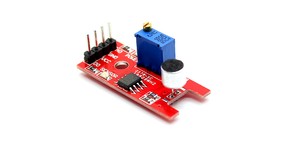
It has four pins that needs to be connected to your Arduino. The top one(if you look at the image above), is AO. This should be connected to the analog input 0 on the Arduino(A0). The one beside that is GND, which is connected to ground, the VCC is connected to +5V, and the last one is DO – which is the digital output of the module, and should be connected to digital pin 2 on the Arduino.
Here is the connection described with a table
| Arduino Pin | Sound Sensor Pins |
|---|
| A0 | AO |
| GND | GND |
| 5V | VCC |
| Digital Pin 2 | DO |
On the top of the sound sensor is a little flathead screw you can turn to adjust the sensitivity and analog output of the sound sensor. To calibrate the sound sensor you can run some music the background and keep turning it until you start seeing the sensor-LED on the module starts blinking with the rhythm.
Connecting the LEDs
Now if you are only going to use one LED, connect your resistor from ground to the shorter side of the LED, and the long side of the LED todigital pin 3 on the Arduino.
If you have even more LEDs, keep doing the same but connect the next one to digital pin 4, the next one to digital pin 5 etc. I’ve written code to support 7 LED lights, which means you use digital pin 3 all the way to 9 for your LEDs. The reason I just didn’t connect the LEDs in parallel and then to only one digital pin, is because on for instance the Uno’s digital pins doesn’t have enough juice to fully power all those power hungry LEDs. You could use a transistor or a 7HC595N, but I just wanted to do a simple sound sensor tutorial so I didn’t include any of that in this post.
So basically Arduino Digital Pin(3-9) –> Positive Side of LED –> Negative Side of LED –> 333 ohm resistor –> Arduino Ground Pin(GND)
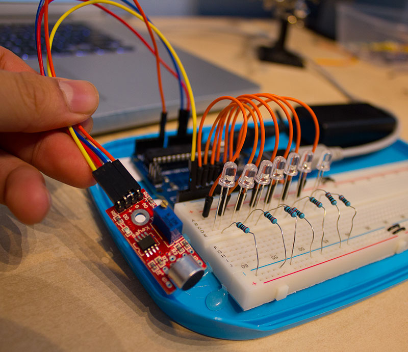
When its all connected it should look something like this
Programming the Arduino
Below is the Arduino code. I don’t count on it to work instantly after uploading the code to your Arduino. It needs some calibration first. But first, copy the code to the Arduino software.
1 2 3 4 5 6 7 8 9 10 11 12 13 14 15 16 17 18 19 20 21 22 23 24 25 26 27 28 29 30 31 32 33 34 35 36 37 38 39 40 41 42 43 44 | int DO = 2; //Pin for Digital Output - DO int DA = A0; // Pin for Analog Output - AO int threshold = 532; //Set minimum threshold for LED lit int sensorvalue = 0; void setup() { //Serial.begin(9600); |


