|
|
Product Picture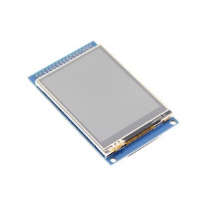 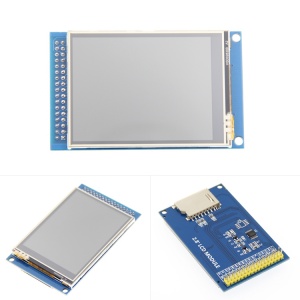
Product Description- 2.8-inch color screen, support 16BIT RGB 65K color display, display rich colors
- 240x320 resolution for clear display
- Support 8-bit/16-bit parallel bus switching (the default is 16-bit), fast transfer speed
- Supports ALIENTEK STM32 Mini, Elite, WarShip, Explorer, and Apollo development boards for direct plug-in use
- Support for touch function
- Support SD card function expansion
- Provides a rich sample program for STM32 and C51 platforms
- Military-grade process standards, long-term stable work
- Provide underlying driver technical support
Product Parameters| Name | Parameter | | Display Color | 16BIT RGB 65K color | | SKU | MRB2801 | | Screen Size | 2.8(inch) | | Screen Type | TFT | | Driver IC | ILI9341 | | Resolution | 320*240 (Pixel) | | Module Interface | 8bit or 16Bit parallel interface | | Active Area | 43.2x57.6 (mm) | | Touch Screen Type | resistive touch screen | | Touch IC | XPT2046 | | Module PCB Size | 51.00x82.55 (mm) | | Operating Temperature | -20℃~60℃ | | Storage Temperature | -30℃~70℃ | | Operating Voltage | 3.3V/5V | | Power Consumption | TBD | | Rough Weight(Package containing) | 44 (g) |
Interface Definition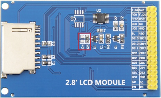
The red box in the above figure is the 8-bit/16-bit data bus mode switch, which is described as follows: - Solder R5 with 0Ω resistor or short circuit directly, and disconnect R4: select 16-bit data bus mode (default), use DB0~DB15 data pin
- Solder R4 with 0Ω resistor or short circuit directly, and disconnect R5: select 8-bit data bus mode, use DB8~DB15 data pin
| Number | Pin Label | Description | | 1 | CS | LCD reset control pin( low level enable) | | 2 | RS | LCD register / data selection control pin(high level: register, low level: data) | | 3 | WR | LCD write control pin | | 4 | RD | LCD read control pin | | 5 | RST | LCD reset control pin( low level reset) | | 6 | DB0 | LCD data bus low 8-bit pin(When 8-bit parallel data bus mode is selected, the lower 8-bit data pins are not used) | | 7 | DB1 | | 8 | DB2 | | 9 | DB3 | | 10 | DB4 | | 11 | DB5 | | 12 | DB6 | | 13 | DB7 | | 14 | DB8 | LCD data bus high 8-bit pin | | 15 | DB9 | | 16 | DB10 | | 17 | DB11 | | 18 | DB12 | | 19 | DB13 | | 20 | DB14 | | 21 | DB15 | | 22 | SDCS | SD card selection control pin (used when using the SD card expansion function, this test program is not used) | | 23 | BL | LCD backlight control pin(High level light) | | 24 | VDD | Module power positive pin (module has integrated voltage regulator IC, so the power supply can be connected to 5V or 3.3V) | | 25 | VDD | | 26 | GND | Module power ground pin | | 27 | GND | | 28 | NC | Undefined, reserved | | 29 | MISO | Touch screen SPI bus data input pin | | 30 | MOSI | Touch screen SPI bus data output pin | | 31 | PEN | Touch screen interrupt detection pin(Low level when a touch occurs) | | 32 | F_CS | Flash chip select control pin (used when using the Flash extension function, this test program is not used) | | 33 | T_CS | Touch screen IC chip select control pin(Low level enable) | | 34 | CLK | Touch screen SPI bus clock control pin |
How to use on STM32 development boardThis module is compatible with the ALIENTEK STM32 development board. The specific usage is as follows: - Step 1: Download the test program
- Download the STM32 test program from the Program Download column
- For a description of the relevant test procedures, please refer to the test program documentation in the package
- Step 2: Connect the STM32 development board
- Find the TFTLCD Slot on the development board, connect the module pins and Slot(For example, the module CS pin corresponds to the slot CS pin),
- and then plug them directly into the Slot
- Step 3: Compile and download the program to the development board
- Compile and download the program you need to test to the STM32 development board( Don't know how to compile and download?)
- Step 4: Observe the running of the program
- After the program is finished, observe the running status of the program. If it can be displayed normally, the program runs successfully.
Program DownloadProduct DocumentationReference MaterialsCommon Software |
|
|
|
|
|
|


